Jan 20 2013
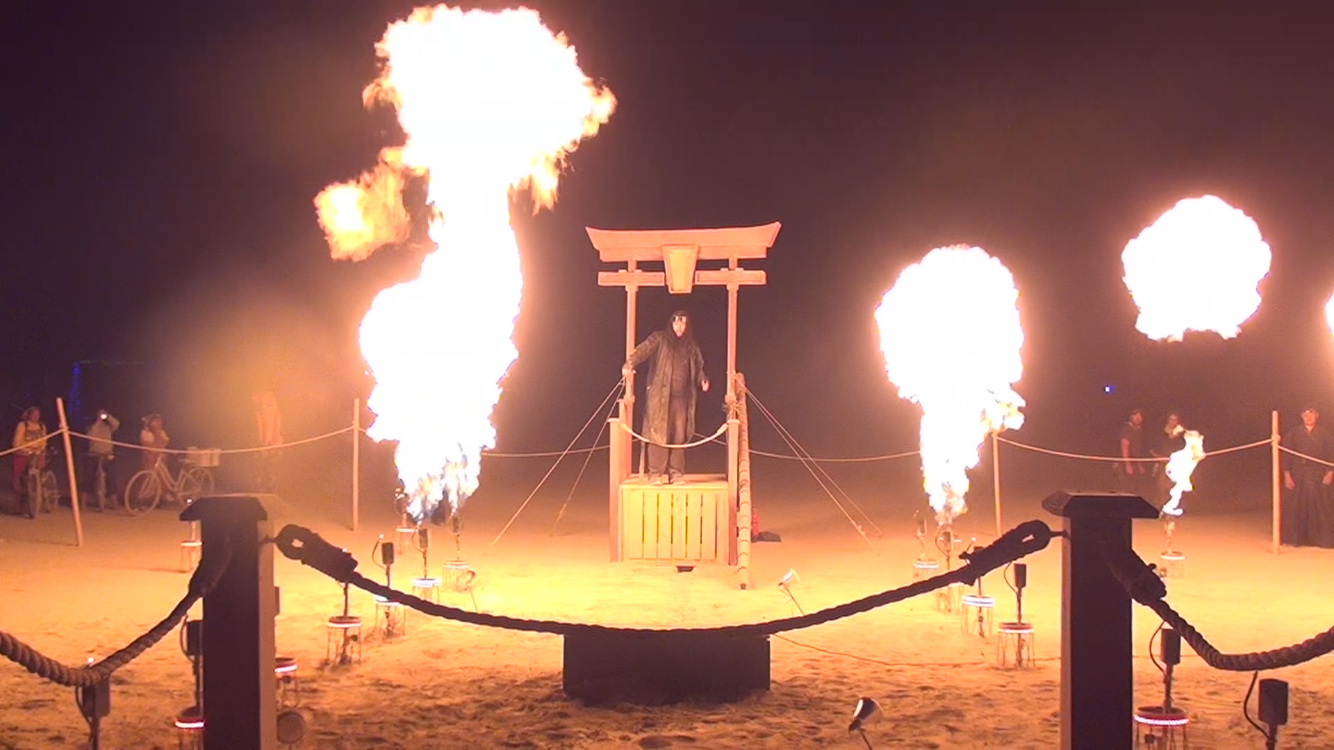
The flame effect system used in Super Street Fire is a ring of 32 flame effects, split up into two inner rails and an outer ring. Participants play the game by wearing motion sensing gloves and throwing punches and other special moves; with each successful gesture, a wave of fire and lights will hurtle towards the other player. The perspective inside the ring looks something like this:
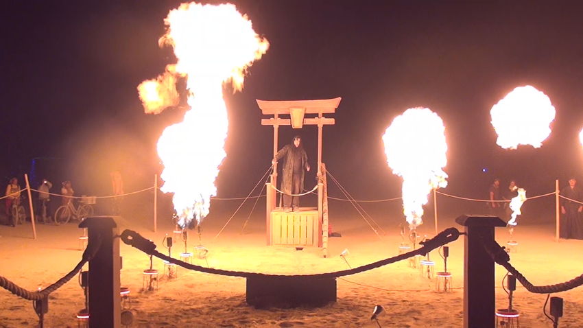
Each effect head has a controller board which operates the fire system, as well as the effect and safety lighting around the protective caps that cover the plumbing. Each cap has a ring of red LEDs that activate when the system is armed, and the caps on the inner rails have blue and green LEDs that correspond to the player activating the flame effect. The control boards are enclosed in plastic containers and buried in the sand to keep them hidden and protect them.

The control system was modeled after the wifire16 solid state relay board, but with a smaller number of outputs, enough to control one flame effect and its safety lighting. The boards have many of the wifire16 features, including full Arduino compatibility, separate system and load power, and reporting back to the microcontroller whether the system is armed. Having one control board per flame effect also meant that the boards could be used to switch AC power to the hot surface igniters from the primary control system.
One of the biggest issues with the SSF v1 installation was that the XBee wireless link was not reliable. To fix this, the new control boards were designed to use a wired RS-485 serial interface. Each board has two RJ-45 connectors for input and output, and a termination header if the board is the last in the chain. The connectors take standard Ethernet cables for ease of setup and reuse.
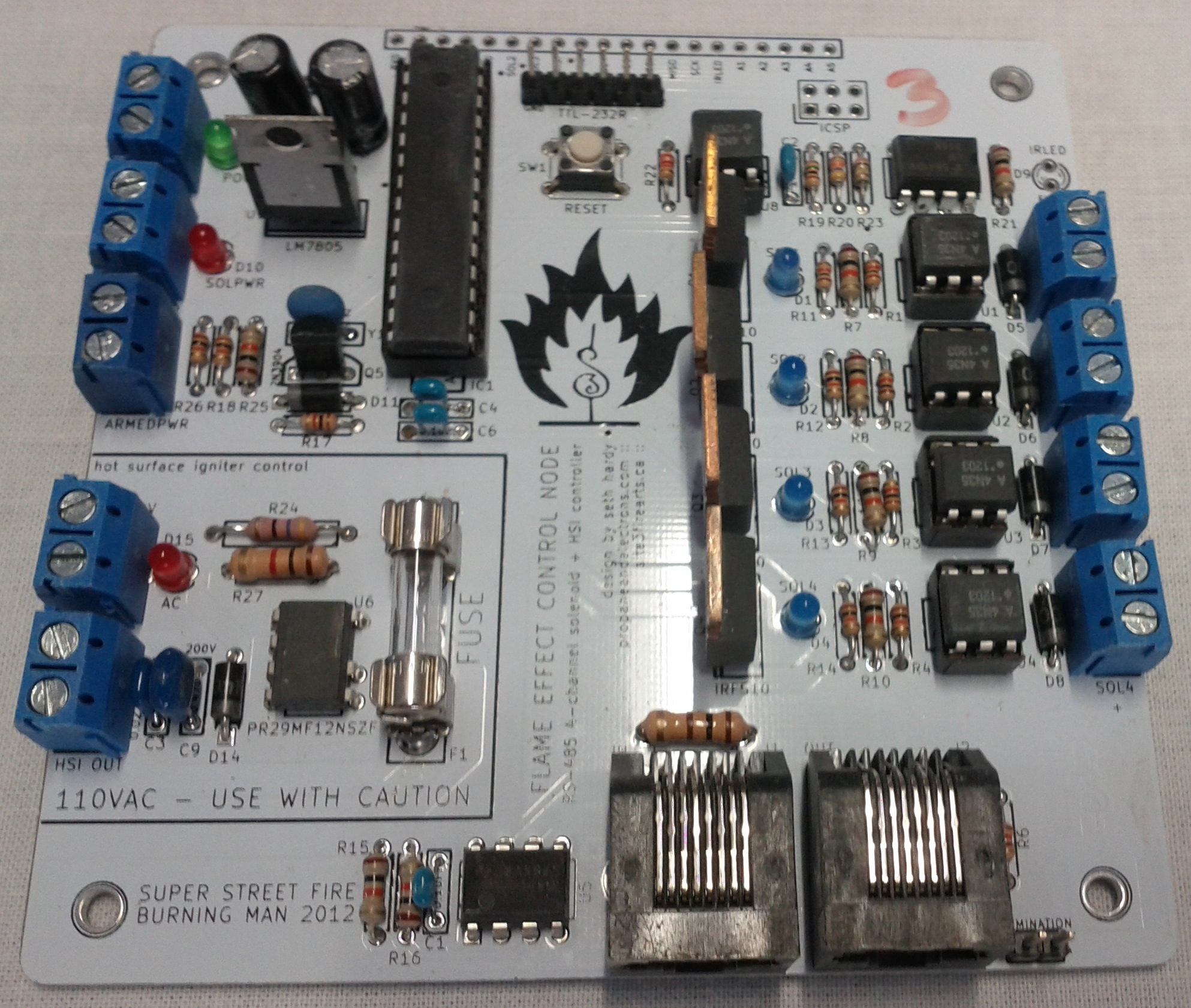
The assembled control nodes look like this:
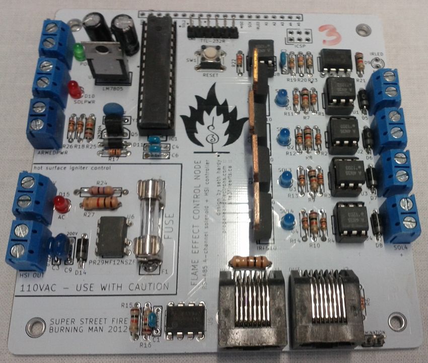
The microcontroller system is in the upper left, the four DC channels are on the right, and the AC system is on the lower left. This was my first design using line voltage AC, so there's a pretty wide gap between the AC system and the rest of the board, and the AC system is on a fuse. The boards also have a built-in flame sensor using an infrared LED. We didn't have the time to implement this functionality in our control software, but it may show up in a future release.
The extra control nodes have since been put to use in a few other projects, as wired control of 4 DC / 1 AC systems has been very useful. The four DC channels all have PWM capability, making the board great for controlling 12v RGB LED strips.
I'm sure I'll be reusing this board for future projects, and hope that other people can find it useful as well for fire and lighting control. Future plans for this board include writing DMX-compatible firmware so that they can be attached to existing DMX networks (for lighting control only, please!). A full writeup of the board will be posted soon in the projects section.
Sep 8 2012
The reason this site has been so silent lately is that I tried to start it up just before starting on version 2 of Super Street Fire. Over the last nine months, I’ve been working with a great team of people to design and build a considerably updated version of the video-game-with-flame-effects and bring it to Burning Man as an honorarium installation.
As part of the project, I designed and built a new flame effects system (fuel heating system, manifold, large regulator, 32 effect heads using hot surface igniters) and the electronics to control it (individual control nodes that take commands over RS-485 and operate the flame effects and LED lighting).
There will be many more posts about SSF and the individual systems coming up, and the flame effect control node design files have already been checked in to the repository. But for now, here is a picture of me riding an accumulator tank wearing someone else’s cowboy hat:

Nov 8 2011
The wifire16 is a 16 channel wireless solid state relay. It acts as an Arduino clone with built-in XBee support, and activates the output channels via shift registers connected to optoisolators and MOSFETs. The output power can use higher voltage DC (within reason, e.g. solenoids that operate at 24 or 48V) as it’s just switched through the board.
The XBee on the wifire16 can run in simple point-to-point (AT) mode. It’s possible for one coordinator in API mode to send commands to many wifire16 boards in AT mode. Each board communicates directly with the coordinator, and the coordinator chooses which board to talk to.
A simple control program that runs on the microcontroller will read one character over the serial link. 0-9 and A-F will toggle channel 1 – 16, and ? will prompt the board to reply with + or – based on whether the solenoid side power is armed. For more complicated applications, the board can be wired in to external sensors.
The end result looks something like this (the final product will have red solder mask):
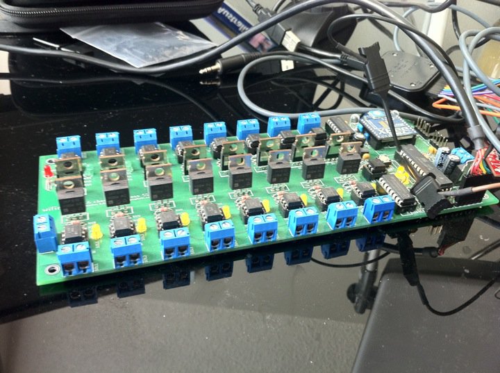
More details on the wifire16 can be found on the project page.
The wifire16 is the heart of Super Street Fire electronics. Currently SSF uses six wifire16 boards: three for fire and color control solenoids, one for 12v LED lighting in the round timer, and two for 12V LED lighting in the player life bars. More on this soon, but here’s a teaser of what the wifire16 boards can control:

Nov 4 2011
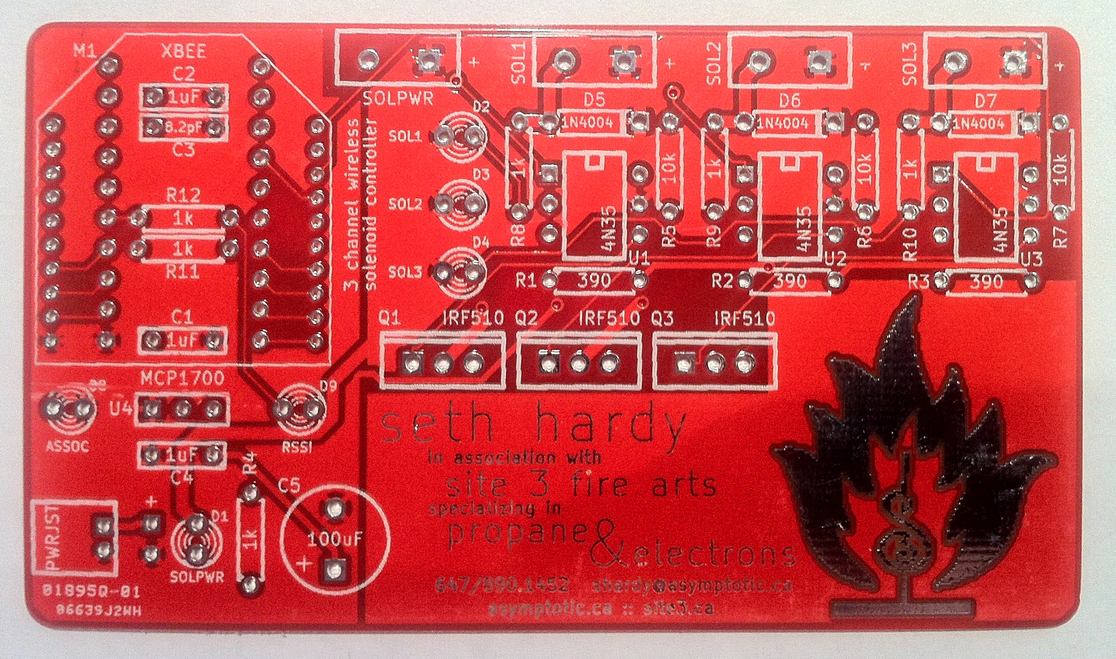
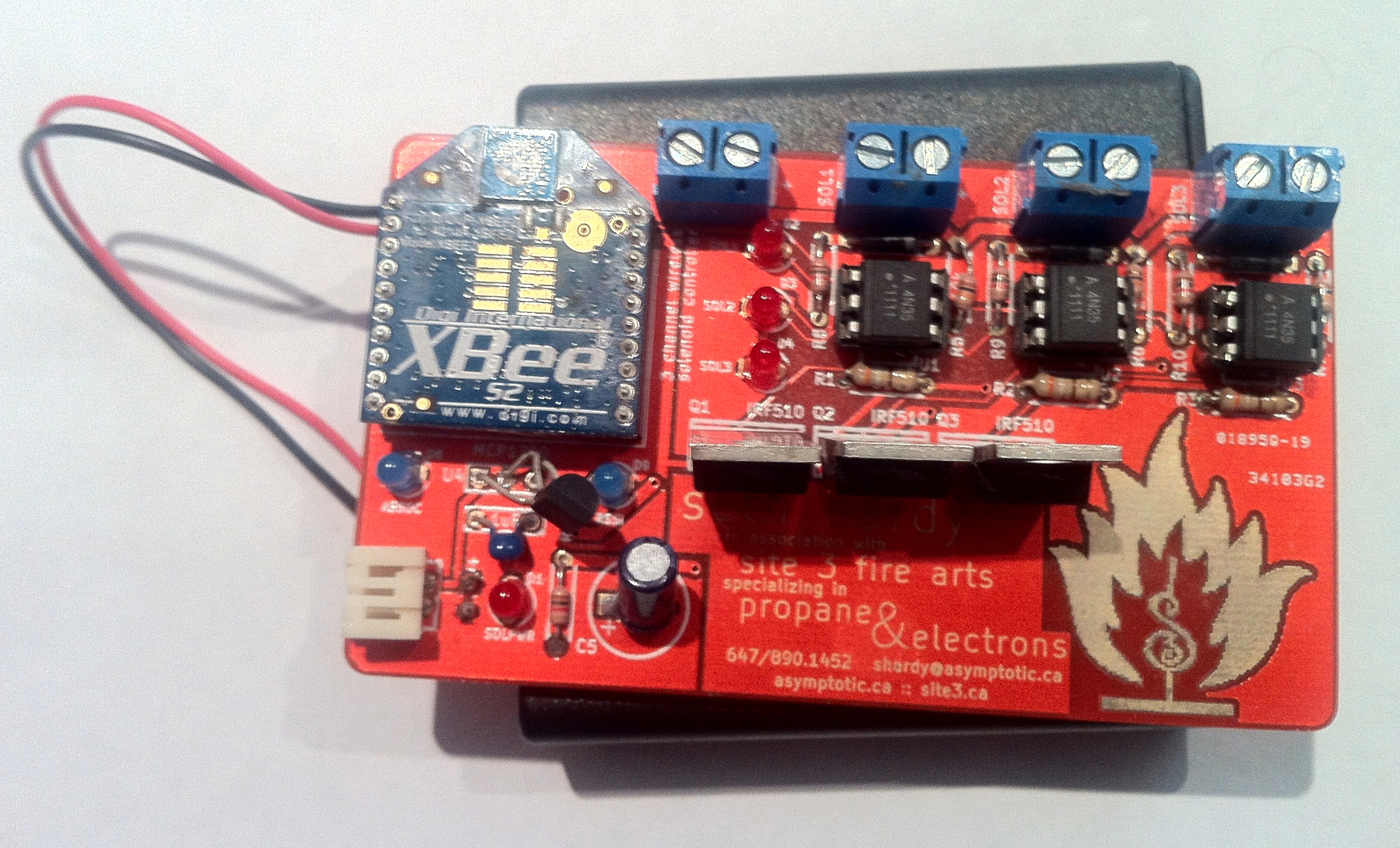
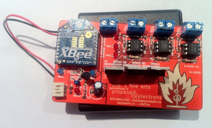
A few months ago, I had the idea of making a PCB business card. At the time I was working on Super Street Fire, and developing a wireless solenoid controller for triggering flame effects. (More on this soon.) I took the same basic idea, removed everything unnecessary (including the microcontroller), and set aside an area for contact info. With the remaining space, I found I could fit three optoisolator/MOSFET circuits comfortably.
The end result is this, a three channel wireless solenoid controller:
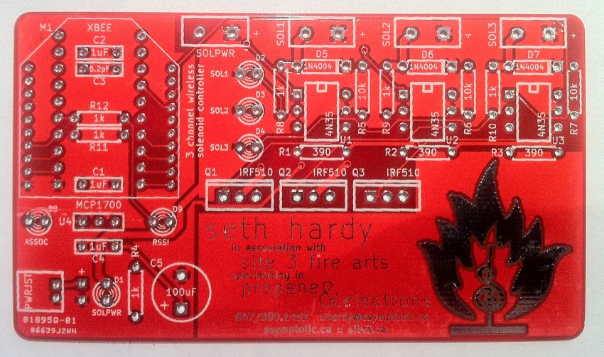
I’ve put up a project page for my business card with more details on the hardware, the KiCad design files, and some example programs to run it.
My hope was to make a memorable card, but also one that’s useful (at least, for other people who create fire art), and one that can be assembled as a project by someone without a lot of electronics experience. I hope that at some point I’ll find someone else’s project using my card as a controller.
I know I’m not the only person who has ever made a PCB business card. However, I’d like to think that mine is particularly awesome; not everyone can say that their business card is a wireless flamethrower controller, and use it to make things that they probably shouldn’t bring across international borders:
“If this were a bomb, would I really have my name, phone number, email address, and website printed on it in a prominent location?”
I hope I don’t ever have to have this conversation.
Nov 2 2011
One of the reasons I decided to make this site is because I am very interested in Open Source Hardware. Arduino is what made me realize that I can do hardware work without a background in electrical engineering; projects like RepRap and commercial ventures like MakerBot Industries have shown me that physical things can be just as accessible for DIY makers as software.
KiCad is an open source EDA (electronic design automation) suite, used for schematic capture and designing PCBs (printed circuit boards). It’s considered to be the “open source equivalent” of EAGLE, another well-known and used program in the OSHW world.
I originally chose KiCad for a simple reason: I was learning how to make PCBs, and while everyone I knew used EAGLE, the board I wanted to make was larger than EAGLE would create with its free version. KiCad was one of the two major alternatives (the other being gEDA), and was the tool that I learned how to do PCB design with.
Over the last three years, I’ve considered switching back to EAGLE and buying a license for it. This is primarily due to the community support for EAGLE, e.g. SparkFun releasing parts libraries and schematics in its format (and requiring it for projects sold through their site).
I’ve decided to stay with KiCad and never made the switch back because I feel very strongly about using free and open source software for open source hardware designs. With the development of EAGLE to KiCad parts converters, the advantage of using EAGLE has been becoming less of an issue; creating new parts in KiCad is also easy and has also never been an issue to stay away from it.
To help encourage other people use KiCad, I’m releasing all of the parts libraries and footprints I create and use in the Google Code repository I’ve set up. I hope that these are of use to other hardware designers and that it helps promote an excellent open source EDA project that I’m happy to have found.
Some Links